FV-1 Instructions and Syntax
For a printable 'cheat-sheet', click here.
EQU
Equate a value to a label reference
| Usage: |
equ |
krt |
0.86 |
;equate the label krt to the value of 0.86 |
| |
equ |
sgn |
-1 |
;equate the label sgn to the value of -1 |
| |
equ |
a |
reg0 |
;equate the label a to represent register 0 |
|
|
|
|
|
| Notes: |
declare label equates prior to label use. |

MEM
Define the length of delay memory elements and associate an address label.
| Usage: |
mem |
del1 |
1000 |
;assign 1000 delay memory locations to the label del1 |
Notes: |
- when writing to a delay, do so to the address label
- when reading the end of the delay, do so to the address label terminated with a #, as in del1#
- when reading the midpoint of a delay, do so to the address label terminated with a $, as in del1$
|
RDA
Read delay memory times coefficient and add to accumulator.
| Usage: |
rda |
memaddress,coefficient |
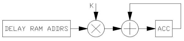
Notes: |
- coefficient width is 11 bits, ranging -2.0 to +1.998
- read data from delay memory is simultaneously loaded into the LR register
- Previous ACC value is simultaneously loaded into PACC
|
RMPA
Read delay memory from addr_ptr location, multiply by coefficient and add to accumulator
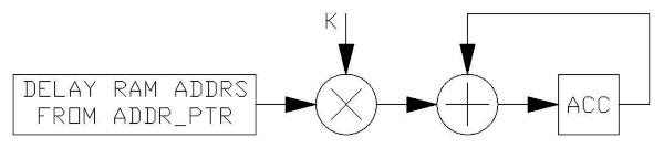
Notes: |
- addr_ptr is a special register reserved for delay memory addressing
- coefficient width is 11 bits, ranging -2.0 to +1.998
- read data from delay memory is simultaneously loaded into the LR register
- Previous ACC value is simultaneously loaded into PACC
|
WRA
Write ACC to delay memory location and multiply ACC by coefficient
| Usage: |
wra |
memaddrs,coefficient |
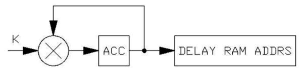
Notes: |
- coefficient width is 11 bits, ranging -2.0 to +1.998
- Previous ACC value is simultaneously loaded into PACC
|
WRAP
Write delay memory, multiply written
value by the coefficient, add to LR register and load ACC with result.
| Usage: |
wrap |
memaddrs,coefficient |
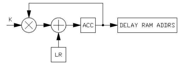
Notes: |
- used specifically in producing inline all pass filters for reverb.
- coefficient width is 11 bits, ranging -2.0 to +1.998
- Previous ACC value is simultaneously loaded into PACC
|
A typical all pass filter is coded with the following sequence, the input signal is assumed to be in ACC, and the output will appear in ACC:
| rda |
ap1#,kap |
| wrap |
ap1,-kap |
where previous statements defined ap1 and kap:
| mem |
ap1 |
205 |
;ap1 is 205 memory locations long |
| equ |
kap |
0.55 |
;all pass coefficient is 0.55 |
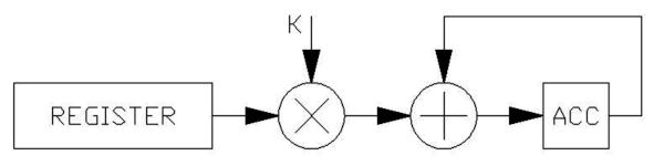
RDAX
Read register value, multiply by coefficient and add to ACC.
| Usage: |
rdax |
reg0,0.2 |
|
rdax |
hifil,kfil |
;hifil previously equated to register (such as reg12), kfil previously equated
to numerical value. |
Notes: |
- coefficient width is 16 bits, ranging -2.0 to +1.9999389
- Previous ACC value is simultaneously loaded into PACC
|
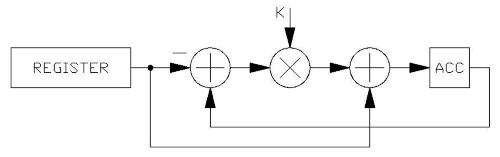
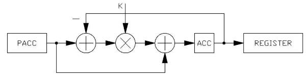
RDFX
Subtract register contents from ACC, multiply by coefficient, add register contents and load to ACC.
Notes: |
- Used specifically for the construction of filters.
- coefficient width is 16 bits, ranging -2.0 to +1.9999389
- Previous ACC value is simultaneously loaded into PACC
- This is a way to load a register directly to the accumulator, using the line:
RDFX reg,1 |
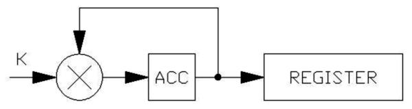
WRAX
Write ACC to register, multiply ACC by coefficient
Notes: |
- Coefficient width is 16 bits, ranging -2.0 to +1.9999389
- Previous ACC value is simultaneously loaded into PACC
|
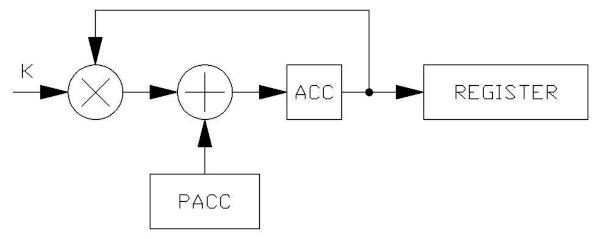
WRHX
Write ACC to register, multiply ACC by coefficient, add PACC and load result to ACC
Notes: |
- Used in creating single pole, shelving high pass filters.
- The coefficient should be negative and will create a shelf gain based on the coefficient value.
- Coefficient width is 16 bits, ranging -2.0 to +1.9999389
- Previous ACC value is simultaneously loaded into PACC
|
The WRHX operation is intended to follow the RDFX operation. An example of a shelving high pass filter follows,
where the input signal is assumed to be in ACC, and the output will appear in ACC after execution:
| rdfx |
reg0,khp |
;khp previously defined with an EQU statement |
| wrhx |
reg0,ksh |
;ksh previously defined with an EQU statement |
The input signal will be in ACC, and during the execution of the first statement, that input signal will be transferred to PACC. During the second instruction, the written value is multiplied by a coefficient (which would be negative for a shelf), and added to PACC (the original input signal). The coefficient in the first instruction sets the corner frequency of the filter, and the coefficient in the second instruction determines the shelf depth. A coefficient of -1.0 represents an infinite shelf, a coefficient of -0.5 sets a shelf at -6dB.
WRLX
Write ACC to the register, subtract ACC from PACC, multiply result by the coefficient, then add PACC and load result
to ACC.
| Usage: |
wrlx |
reg6,kshlf |
;kshlf previously equated to a numerical value. |
Notes: |
- Used in creating single pole, shelving low pass filters.
- The coefficient should be negative and will create a shelf gain based on the coefficient value.
- Coefficient width is 16 bits, ranging -2.0 to +1.9999389
- Previous ACC value is simultaneously loaded into PACC
|
The WRLX operation is intended to follow the RDFX operation. An example of a shelving low pass filter follows, where the input signal is assumed to be in ACC, and the output will appear in ACC after execution:
| rdfx |
reg0,klp |
;klp previously defined with an EQU statement |
| wrlx |
reg0,ksh |
;ksh previously defined with an EQU statement |
The input signal will be in ACC, and during the execution of the first statement, that input signal will be transferred to PACC. During the second instruction, the written value is subtracted from PACC (the filter's input signal), multiplied by the shelving coefficient and added to PACC (the original input signal). The coefficient in the first instruction sets the corner frequency of the filter, and the coefficient in the second instruction determines the shelf depth. A coefficient of -1.0 represents an infinite shelf, a coefficient of -0.5 sets a shelf at
-6dB.
MAXX
Load the maximum of the absolute value of the register times the coefficient or the absolute value of ACC to ACC.
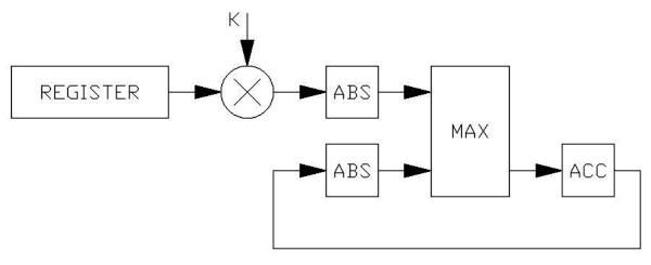
Notes: |
- Coefficient width is 16 bits, ranging -2.0 to +1.9999389
- Previous ACC value is simultaneously loaded into PACC
- Maxx is ideal for delivering a peak detected signal to a low pass filter; if the signal is in the accumulator and reg0 is used as a filter:
maxx reg0,0.99
wrax reg0,0
|
The first instruction compares the value in reg0 with the accumulator, but does so with a somewhat decreased reg0 value; this is so that if the ACC signal is smaller, the second instruction will write this decreased value back to reg0. Otherwise, the ACC value will be forced into reg0. The coefficient in the second instruction leaves ACC cleared, but if the coefficient is 1, then the peak detected signal will be passed on to further processing. The coefficient in the first instruction will determine the time constant of the filter.
ABSA
Changes the ACC contents to absolute value of ACC
| Notes: |
Previous ACC value is simultaneously loaded into PACC |
MULX
Load the accumulator with the product of ACC and a register.
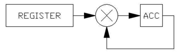
Notes: |
- The upper 15 bits of the register are used as a coefficient, allowing a multiplier range of -1.0 to +0.999389
- Previous ACC value is simultaneously loaded into PACC
|
LOG
Take the LOG base 2 of the absolute value of the accumulator, divide result by 16, multiply the result by the coefficient, add a constant and load to ACC.
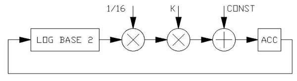
Notes: |
- Coefficient width is 16 bits, ranging -2.0 to +1.9999389
- constant width is 11 bits, -1.0 to +0.999
- Previous ACC value is simultaneously loaded into PACC
- This function, along with EXP provides the ability to perform divides and square roots.
|
Because the maximum value that can be input to the LOG function is +1.0, the maximum LOG output value is 0; most real arguments will deliver a negative LOG result. Since the negative result value could be quite large for very small input arguments, the scale for the LOG result is divided by 16 at it's output, for storage in the -1 to +0.9999 signal range of registers.
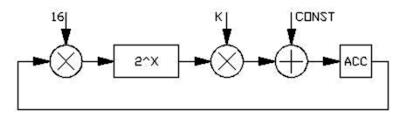
EXP
Raise 2 to the power of the accumulator*16, multiply by a coefficient and add to a constant, loading the result to ACC.
Notes: |
- Coefficient width is 16 bits, ranging -2.0 to +1.9999389
- constant width is 11 bits, -1.0 to +0.999
- Previous ACC value is simultaneously loaded into PACC
- This function, along with LOG provides the ability to perform divides and square roots.
- The EXP function is designed tocompliment the LOG function.
|
Because the maximum value that can be input to the LOG function is +1.0, the maximum LOG output value is 0; most real arguments will deliver a negative log result. Since the negative result value could be quite large for very small input arguments, the scale for the LOG
result is divided by 16 at it's output, for storage in the -1 to +0.9999 signal range of registers.
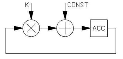
SOF
Multiply ACC by the coefficient value and add a constant (Scale and OFfset)
| Usage: |
SOF |
1.5,-0.3 |
;multiply the accumulator by 1.5 and subtract 0.3 |
Notes: |
- Coefficient width is 16 bits, ranging -2.0 to +1.9999389
- constant width is 11 bits, -1.0 to +0.999
- Previous ACC value is simultaneously loaded into PACC
|
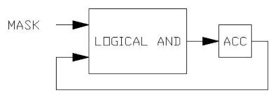
AND
And ACC with immediate mask
| Usage: |
and |
%011111000000000000000000 |
;and with binary 011111000000000000000000 |
|
and |
$000001 |
;and with hex 000001 |
| Notes: |
Previous ACC value is simultaneously loaded into PACC |
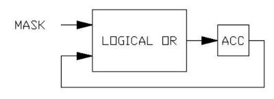
OR
Or ACC with immediate mask
| Usage: |
or |
%011111000000000000000000 |
;or with binary 011111000000000000000000 |
|
or |
$000001 |
;or with hex 000001 |
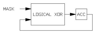
XOR
Xor ACC with immediate mask
| Usage: |
xor |
%011111000000000000000000 |
;or with binary 011111000000000000000000 |
|
xor |
$000001 |
;or with hex 000001 |
| Notes: |
Previous ACC value is simultaneously loaded into PACC |
SKP
Skip N instructions based on condition
| Usage: |
skp |
zro,2 |
;skip ahead 2 instructions if accumulator is zero. |
|
skp |
gez,doit |
;skip to label doit if accumulator is zero or positive |
| Notes: |
Conditions are: |
|
run |
;set after first program execution |
|
zrc |
;if the sign of ACC and PACC are different |
|
zro |
;if ACC is zero |
|
gez |
;if ACC is greater than or equal to zero |
|
neg |
;if ACC is negative |
WLDS
Load SIN/COS generator with initial conditions
| Usage: |
wlds |
sin0,freq,amp |
;load the SIN/COS0 generator with freq and amp variables |
Notes: |
- There are two SIN/COS generators in the FV-1, SIN0 and SIN1
- The frequency variable is a 9 bit value
- The amplitude variable is a 15 bit value
- This command is usually used to initialize a SIN/COS generator at the beginning of the program, preceded by a
Skp run,1 command.
|
WLDR
Load RAMP generator with initial conditions
| Usage: |
wldr |
rmp0,freq,amp |
;load the RAMP0 generator with freq and amp variables |
Notes: |
- There are two RAMP generators in the FV-1, RMP0 and RMP1
- The frequency variable is a 16 bit value
- The frequency variable is a 2 bit value 00 (0)=512, 01 (1)=1024, 10 (2)=2048 and 11 (3)=4096
- This command is usually used to initialize a RAMP generator at the beginning of the program, preceded by a Skp run,1 command.
|
JAM
When executed, will force a selected RAMP generator to it's starting condition
Notes: |
- This can be used in pitch transposition to intelligently reset the read pointer when the input
- and output of the transpose function are highly correlated.
|
CHO
General operation for reading delay memory from an LFO output as both a memory pointer and an interpolation coefficient.
| Usage: |
cho |
rda,sin0, SIN | REG ,del1+100 |
;read del1+100+(sine of SIN/COS0 value) also, register LFO values. |
|
cho |
rdal,sin1 |
;load accumulator with SIN/COS1 LFO output (Sine only) |
|
cho |
sof,rmp1,na |
;multiply ACC value by ramp1 crossfade value |
The CHO operations allow the LFOs to supply address and coefficient information the the FV-1 engine, and are complicated by their flexibility. The three variants, RDA, RDAL and SOF have specific usage. LFO selection can be either sin0 or sin1 (the two SIN/COS LFOs, or
rmp0 or rmp1 (the two RAMP LFOs).
The CHO RDA operation is intended to read memory from a location specified by the user, plus an address value from the selected LFO. The addressed value is multiplied by a fractional coefficient to form half of a signal interpolation between two adjacent points. The values
from the LFO can be modified by a 6 bit number, inserted into the command line, that direxcts the process in several ways. The bits can be manually assembled into a number that is entered in decimal, HEX($-) or binary(%-). The 6 bits are as follows:
- Bit0: SIN (000000) or COS (000001) selects either the SIN or COS output of a SIN/COS generator
- Bit1: REG (000010) function. Using this will register the current LFO outputs for subsequent operations; to be used only on the first access to an LFO (LFO is continuously updated in the background)
- Bit2: COMPC(000100) sends 1-fraction to the multiplier for the first half of an interpolation.
- Bit3: COMPA(001000) compliments the address output, effectively inverting the SIN or COS function.
- Bit4: RPTR2(010000) Adds 0.5 of full scale to a RAMP, to obtain a second pointer in pitch transpose operations
- Bit5: NA(100000) Selects the crossfade function of a ramp generator for crossfading in a pitch transposer.
The above bits can be used in OR fashion, such as: CHO RDA,S0,COS|REG|COMPC,del1+20
SIN/COS LFOs can only use bits 0, 1, 2 and 3, while RAMP LFOs make use of bits 1, 2, 3, 4, and 5.
NOP
No operation
NOT
Change sign of ACC value
| Notes: |
Previous ACC value is simultaneously loaded into PACC |
CLR
Clear ACC
| Notes: |
Previous ACC value is simultaneously loaded into PACC |